ENGINEERING MATHEMATICS
Linear Algebra: Matrix Algebra, Systems of linear equations, Eigen values and eigen vectors.
Calculus: Mean value theorems, Theorems of integral calculus, Evaluation of definite and improper integrals, Partial Derivatives, Maxima and minima, Multiple integrals, Fourier series. Vector identities, Directional derivatives, Line, Surface and Volume integrals, Stokes, Gauss and Green’s theorems.
Differential equations: First order equation (linear and nonlinear), Higher order linear differential equations with constant coefficients, Method of variation of parameters, Cauchy’s and Euler’s equations, Initial and boundary value problems, Partial Differential Equations and variable separable method.
Complex variables: Analytic functions, Cauchy’s integral theorem and integral formula, Taylor’s and Laurent’ series, Residue theorem, solution integrals.
Probability and Statistics: Sampling theorems, Conditional probability, Mean, median, mode and standard deviation, Random variables, Discrete and continuous distributions, Poisson, Normal and Binomial distribution, Correlation and regression analysis.
Numerical Methods: Solutions of non-linear algebraic equations, single and multi-step methods for differential equations.
Transform Theory: Fourier transform, Laplace transform, Z-transform.
ELECTRONICS AND COMMUNICATION ENGINEERING
Networks: Network graphs: matrices associated with graphs; incidence, fundamental cut set and fundamental circuit matrices. Solution methods: nodal and mesh analysis. Network theorems: superposition, Thevenin and Norton’s maximum power transfer, Wye-Delta transformation. Steady state sinusoidal analysis using phasors. Linear constant coefficient differential equations; time domain analysis of simple RLC circuits, Solution of network equations using Laplace transform: frequency domain analysis of RLC circuits. 2-port network parameters: driving point and transfer functions. State equations for networks.
Electronic Devices: Energy bands in silicon, intrinsic and extrinsic silicon. Carrier transport in silicon: diffusion current, drift current, mobility, and resistivity. Generation and recombination of carriers. p-n junction diode, Zener diode, tunnel diode, BJT, JFET, MOS capacitor, MOSFET, LED, p-I-n and avalanche photo diode, Basics of LASERs. Device technology: integrated circuits fabrication process, oxidation, diffusion, ion implantation, photolithography, n-tub, p-tub and twintub CMOS process.
Analog Circuits: Small Signal Equivalent circuits of diodes, BJTs, MOSFETs and analog CMOS. Simple diode circuits, clipping, clamping, rectifier. Biasing and bias stability of transistor and FET amplifiers. Amplifiers: single-and multi-stage, differential and operational, feedback, and power. Frequency response of amplifiers. Simple op-amp circuits. Filters. Sinusoidal oscillators; criterion for oscillation; single-transistor and op-amp configurations. Function generators and waveshaping circuits, 555 Timers. Power supplies.
Digital circuits: Boolean algebra, minimization of Boolean functions; logic gates; digital IC families (DTL, TTL, ECL, MOS, CMOS). Combinatorial circuits: arithmetic circuits, code converters, multiplexers, decoders, PROMs and PLAs. Sequential circuits: latches and flip-flops, counters and shift-registers. Sample and hold circuits, ADCs, DACs. Semiconductor memories. Microprocessor(8085): architecture, programming, memory and I/O interfacing.
Signals and Systems: Definitions and properties of Laplace transform, continuous-time and discrete-time Fourier series, continuous-time and discrete-time Fourier Transform, DFT and FFT, z-transform. Sampling theorem. Linear Time-Invariant (LTI) Systems: definitions and properties; causality, stability, impulse response, convolution, poles and zeros, parallel and cascade structure, frequency response, group delay, phase delay. Signal transmission through LTI systems.
Control Systems: Basic control system components; block diagrammatic description, reduction of block diagrams. Open loop and closed loop (feedback) systems and stability analysis of these systems. Signal flow graphs and their use in determining transfer functions of systems; transient and steady state analysis of LTI control systems and frequency response. Tools and techniques for LTI control system analysis: root loci, Routh-Hurwitz criterion, Bode and Nyquist plots. Control system compensators: elements of lead and lag compensation, elements of Proportional-Integral- Derivative (PID) control. State variable representation and solution of state equation of LTI control systems.
Communications: Random signals and noise: probability, random variables, probability density function, autocorrelation, power spectral density. Analog communication systems: amplitude and angle modulation and demodulation systems, spectral analysis of these operations, superheterodyne receivers; elements of hardware, realizations of analog communication systems; signal-to-noise ratio (SNR) calculations for amplitude modulation (AM) and frequency modulation (FM) for low noise conditions. Fundamentals of information theory and channel capacity theorem. Digital communication systems: pulse code modulation (PCM), differential pulse code modulation (DPCM), digital modulation schemes: amplitude, phase and frequency shift keying schemes (ASK, PSK, FSK), matched filter receivers, bandwidth consideration and probability of error calculations for these schemes. Basics of TDMA, FDMA and CDMA and GSM.
Electromagnetics: Elements of vector calculus: divergence and curl; Gauss’ and Stokes’ theorems, Maxwell’s equations: differential and integral forms. Wave equation, Poynting vector. Plane waves: propagation through various media; reflection and refraction; phase and group velocity; skin depth. Transmission lines: characteristic impedance; impedance transformation; Smith chart; impedance matching; S parameters, pulse excitation. Waveguides: modes in rectangular waveguides; boundary conditions; cut-off frequencies; dispersion relations. Basics of propagation in dielectric waveguide and optical fibers. Basics of Antennas: Dipole antennas; radiation pattern; antenna gain.
|
Monday 28 May 2012
GATE SYLLABUS FOR ECE
Sunday 27 May 2012
Wednesday 23 May 2012
Monday 21 May 2012
iPhone Camera Provides Live Image to Car Navigation System
Fujitsu Ten Ltd developed an application software that displays video being taken by the camera of an iPhone on the screen of a car navigation system and superimposes icons on the video to navigate the driver to the destination.

To use the software, "Driview," an iPhone is connected to Fujitsu Ten's stationary car navigation system by using a separately-sold cable. The company made the application available on the App Store for free May 16, 2012.
Driview can be used with the "AVN-ZX02i" and "AVN-Z02i," which are car navigation systems that Fujitsu Ten sells under the "Eclipse" brand. It not only shows route information on video taken by an iPhone but adds location information to the video and saves it.
Fujitsu Ten Ltd developed an application software that displays video being taken by the camera of an iPhone on the screen of a car navigation system and superimposes icons on the video to navigate the driver to the destination.
To use the software, "Driview," an iPhone is connected to Fujitsu Ten's stationary car navigation system by using a separately-sold cable. The company made the application available on the App Store for free May 16, 2012.
Driview can be used with the "AVN-ZX02i" and "AVN-Z02i," which are car navigation systems that Fujitsu Ten sells under the "Eclipse" brand. It not only shows route information on video taken by an iPhone but adds location information to the video and saves it
Electronics Makers Move into Medical, Healthcare
 Electronics manufacturers are beginning to show keen interest in the medical and health field, because from 2006 the number of areas they can play a part in has been growing fast (Fig 1).
"We're approaching a turning point in the medical field where technology from our industry will spread exceedingly rapidly," said Masahiko Itagoshi, director, Digital Health Business Development Group, Solution & Business Development Group of Intel Corp of the US.
Yasuo Sugihara, deputy manager, Development Planning Group, Products Development Center, Toshiba Consumer Marketing Corp of Japan, added, "The health sector represents a major business opportunity. It will unquestionably grow."
Little Growth in Past
In the past, the very latest electronic components and other electronics technologies have been adopted for use in medical equipment in the medical and health fields, but the market for such equipment has always been fairly stable, without experiencing any dramatic growth. In addition, it has been a difficult goal for equipment and component manufacturers entering the field for the first time. Even if electronic equipment manufacturers want to release new products, the licensing and approval system imposed by the Pharmaceutical Affairs Law requires quality and safety assessments that are even tougher for newer technologies. This means greater risks for the manufacturer, in the form of unexpected costs and delays, before a product can be released. Component manufacturers, meanwhile, have to fulfill these demands from equipment manufacturers, and generally consider the medical equipment market as having an excessive number of quality and safety requirements in comparison to product volume and value benefits.
 In Japan, the situation is beginning to change, though, because from 2006 electronics manufacturers are closer than ever to the medical and health field (Fig 2).
Stated Policy Goal
The first key point is the announced policy goal of applying information technology to restructure medicine, as spelled out in the e-Japan Priority Policy Program 2006, announced at the end of July 2006 by the IT Strategic Headquarters of the Japanese cabinet. This document is also accelerating the trend toward transferring patients from core hospitals to local facilities or homes, as far as is possible, and utilizing health information acquired in the home to prevent medical problems. This will mean a market growth from the (approximately) 9,000 hospitals at present to some 48 million households: the same quantity as for household appliances.
Significant market growth is expected in equipment, services and other products not covered by the Pharmaceutical Affairs Law, and it is likely that electronics manufacturers will be able to apply the technologies developed in digital household appliances and other fields.
Streamlining Procedures
Second, there is activity to streamline the licensing procedures under the Pharmaceutical Affairs Law. The Ministry of Economy, Trade & Industry (METI) and other organizations plan to complete guidelines for medical equipment development before the end of fiscal 2006, defining assessment indices and criteria applying to the Pharmaceutical Affairs Law. The stated objective is to promote new entry into the medical equipment field, with special interest in new entry from the electronics industry. Such guidelines have not existed in the past, representing a major load for companies trying to enter the field.
New Opportunities
Third, medical equipment manufacturers are getting ready to handle the new market expansion created by these developments. GE Yokogawa Medical Systems, Ltd of Japan, for example, released a compact ultrasound diagnostic system for obstetrics and gynecology use, about the size of a notebook personal computer (PC), in May 2006. The firm hopes to develop a new market, allowing physicians to visit patients, carrying the diagnostic system. This type of medical equipment manufacturer is interested in high-performance semiconductors, electronic components and other items that will make it possible to improve equipment size and other characteristics.
As engineers at several medical equipment manufacturers have commented, indicating their hopes for new business in medical electronics, "If some firms have component technologies ahead of the curve, we want to know about them fast."
Home-Use Technologies
In fact, a growing number of electronics manufacturers have recognized the changing situation as a business opportunity.
Hitachi Ltd of Japan, for example, released a watch-type sensor measuring pulse and other items, positioned as a measuring instrument for home-use health management, in early 2006. Toshiba Consumer Marketing now offers a service providing medical advice from physicians based on data including body fat, blood pressure and electrocardiogram (ECG) waveforms measured at home.
With the market moving ever closer to the home, there is an increasing number of examples of companies entering the health field while maintaining existing relationships with the household appliance world. Apple Computer, Inc of the US and Nike, Inc of the US, for example, will release a line of health-management products, using a shoe-mounted sensor to measure health information and transmit it to an iPod nano for management, in July 2006 in the US and September 2006 in Japan. Matsushita Electric Works, Ltd of Japan has proposed a system for comfortable sleeping, controlling lighting, audio-visual (AV) equipment, air conditioners and other systems to match a person's sleeping state.
At International Modern Hospital Show 2006, the medical and health exhibition held in July 2006, Nanao Corp of Japan exhibited a system to transmit emergency diagnostic imagery to specialists at remote locations, using an image transfer/remote control technology developed in-house. NEC LCD Technologies, Ltd of Japan forecasts growth in liquid crystal display (LCD) panels as electronic patient records become more common, and had a booth at the same show. These are only a few examples, but there are many more.
Digitizing Information
A closer look at the activities of electronics manufacturers reveals a common objective: recognition of a major business opportunity in the expanding application of information, especially digital information. Many manufacturers in the medical equipment sector agree that enormous market growth is possible, because the medical and health field is probably the industry lagging farthest behind when it comes to applying electronics technology to information.
The national policy position of applying information technology to restructure medicine, as mentioned above, demonstrates strong government support for the move. In the health field, for example, a framework is being planned to systematically manage individual health data acquired in the home and utilize it to prevent illness. In the medical field the widespread adoption of electronic patient records and remote medicine is driving the construction of an efficient medical system linking hospitals to clinics and homes. This represents the perfect opportunity for electronics manufacturers searching for a new market to follow existing major markets such as digital appliances or automobiles. Matsushita Electric Industrial Co, Ltd of Japan has positioned the healthcare sector as another major business sector, following flat-panel televisions, according to Kimio Minami, general manager, Healthcare Systems Development Office at Matsushita Electric Industrial. The firm established the office in April 2006.
 In fact, information has only just really begun to be utilized in the medical and health fields. For example, the government's plan to leverage information technology and restructure medicine calls for the complete shift to online receipt systems by the start of 2011. As of 2005, only about 10% of hospitals and 4% of clinics have online systems (Fig 3). National policy calls for an increase to 100% within only a few years. This degree of abrupt transformation is occurring in many places.
 Supporting the Future
While officials are calling for the utilization of digital information in medicine and health, advances are likely to be on an individual basis for some time to come. For example, while health information may be measured at home, no methods have been established to define how to analyze it or use it to prevent illness. A number of medical equipment manufacturers agree that physicians cannot utilize health information acquired at home until it is significantly more accurate and detailed.
 In the near future, though, efforts to utilize digital information in the medical and health fields will fuse (Fig 4). A source at Toshiba Medical Systems Corp of Japan believes that treatment, diagnostic and health information for a given individual will be stored in a single server, with medical equipment and analysis systems acting as tools (sensors) to input the latest information.
 Electronics manufacturers will play a major role in realizing this goal in the near future, and some are already in action. In 2006, Intel and other firms began development of a communications protocol to link diverse measurement instruments, with the goal of systematic management of information acquired in the home.
High expectations for electronics technology are evident in personnel development programs, too. The Tohoku University Biomedical Engineering Research Organization (TUBERO), established in July 2003, said the future will demand a fusion of medicine and engineering, not merely the close cooperation they enjoy at present, and hopes to train "biomedical engineers" capable of serving as both physicians and technologists. The Graduate School of Biomedical Engineering is scheduled to be established in the School of Engineering in April 2008 to train such specialists ....../documents/large_document.pdf <a href="/documents/large_document.pdf">Download the large document</a>
/documents/large_document.pdf
Download the large document
Right-click the link and choose "Save Link As..." to save the document to your computer

Thursday 17 May 2012
Digital Community Channel Transmitter
CT-101
Digital Community Channel Transmitter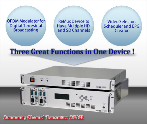
The CT-101 Digital Community Channel Transmitter is a new-concept device to transmit community channels for CATV broadcasting. OFDM modulator, ReMux device and Scheduler are equipped with the compact device and a variety of programming of community channels will be realized.
In addition, programs can be transmitted in the form of MPEG2-TS data, saving much time and cost.
In addition, programs can be transmitted in the form of MPEG2-TS data, saving much time and cost.
 *1 AAC-101 is a unit to convert MPEG1, the audio data used with video editor software, into AAC, the one for digital terrestrial broadcasting.
*2 CAC-010 is a unit to convert parallel signals from sattelites into DVB-ASI (serial) signals. Dimensions: 126 x 96 x 30mm
General Specifications
| Input port | Number of ports: 7 Interface: DVB-ASI |
|---|---|
| Output port | Number of ports: 1 Interface: OFDM (5.6MHz) |
| Modulation system: QPSK / 16QAM / 64QAM | |
| AC line | AC100 V±10% (50/60 Hz) / 100W 以下 |
| Ambience | 10 to 40 degree C |
| Dimensions | CT-101 main body 480 (W) × 99 (H) × 400 (D) mm |
| AAC-101 480 (W) × 49 (H) × 370 (D) mm |
■Scheduler
■Configuration
■Monitoring
Crusoe Processor
Mobile computing has been the buzzword for quite a long time. Mobile
computing devices like laptops, webslates & notebook PCs are
becoming common nowadays. The heart of every PC whether a desktop or
mobile PC is the microprocessor. Several microprocessors are available
in the market for desktop PCs from companies like Intel, AMD, Cyrix
etc.The mobile computing market has never had a microprocessor
specifically designed for it. The microprocessors used in mobile PCs are
optimized versions of the desktop PC microprocessor. Mobile computing
makes very different demands on processors than desktop computing, yet
up until now, mobile x86 platforms have simply made do with the same old
processors originally designed for desktops. Those processors consume
lots of power, and they get very hot. When you’re on the go, a
power-hungry processor means you have to pay a price: run out of power
before you’ve finished, run more slowly and lose application
performance, or run through the airport with pounds of extra batteries. A
hot processor also needs fans to cool it; making the resulting mobile
computer bigger, clunkier and noisier. A newly designed microprocessor
with low power consumption will still be rejected by the market if the
performance is poor. So any attempt in this regard must have a proper
‘performance-power’ balance to ensure commercial success. A newly
designed microprocessor must be fully x86 compatible that is they should
run x86 applications just like conventional x86 microprocessors since
most of the presently available software’s have been designed to work on
x86 platform.
Crusoe is the new microprocessor which has been designed specially for the mobile computing market. It has been designed after considering the above mentioned constraints. This microprocessor was developed by a small Silicon Valley startup company called Transmeta Corp. after five years of secret toil at an expenditure of $100 million. The concept of Crusoe is well understood from the simple sketch of the processor architecture, called ‘amoeba’. In this concept, the x86-architecture is an ill-defined amoeba containing features like segmentation, ASCII arithmetic, variable-length instructions etc. The amoeba explained how a traditional microprocessor was, in their design, to be divided up into hardware and software.
Thus Crusoe was conceptualized as a hybrid microprocessor that is it has a software part and a hardware part with the software layer surrounding the hardware unit. The role of software is to act as an emulator to translate x86 binaries into native code at run time. Crusoe is a 128-bit microprocessor fabricated using the CMOS process. The chip’s design is based on a technique called VLIW to ensure design simplicity and high performance. Besides this it also uses Transmeta’s two patented technologies, namely, Code Morphing Software and Longrun Power Management. It is a highly integrated processor available in different versions for different market segments.
Technology Perspective
The Transmeta designers have decoupled the x86 instruction set architecture (ISA) from the underlying processor hardware, which allows this hardware to be very different from a conventional x86 implementation. For the same reason, the underlying hardware can be changed radically without affecting legacy x86 software: each new CPU design only requires a new version of the Code Morphing software to translate x86 instructions to the new CPU’s native instruction set. For the initial Transmeta products, models TM3120 and TM5400, the hardware designers opted for minimal space and power. By eliminating roughly three quarters of the logic transistors that would be required for an all-hardware design of similar performance, the designers have likewise reduced power requirements and die size. However, future hardware designs can emphasize different factors and accordingly use different implementation techniques. Finally, the Code Morphing software which resides in standard Flash ROMs itself offers opportunities to improve performance without altering the underlying hardware.
Ultra Wide Band Technology
Ultra Wide Band (UWB) is a
revolutionary technology with incomparable potential in terms of
throughput, performance and low cost implementation. The uniqueness of
UWB is that it transmits across extremely wide bandwidth of several GHz,
around a low center frequency, at very low power levels.
UWB is fundamentally different from existing radio frequency
technology. For radios today, picture a guy watering his lawn with a
garden hose and moving the hose up and down in a smooth vertical motion.
You can see a continuous stream of water in an undulating wave. Nearly
all radios, cell phones, wireless LANs and so on are like that: a
continuous signal that’s overlaid with information by using one of
several modulation techniques. Now picture the same guy watering his
lawn with a swiveling sprinkler that shoots many, fast, short pulses of
water. That’s typically what UWB is like: millions of very short, very
fast, precisely timed bursts or pulses of energy, measured in
nanoseconds and covering a very wide area. By varying the pulse timing
according to a complex code, a pulse can represent either a zero or a
one: the basis of digital communications.UWB is almost two decades old, but is used mainly in limited radar or position-location devices. Only recently has UWB been applied to business communications. It’s a different type of transmission that will lead to low-power, high-bandwidth and relatively simple radios for local- and personal-area network interface cards and access points. At higher power levels in the future, UWB systems could span several miles or more.
Wireless technologies such as 802.11b and short-range Bluetooth radios eventually could be replaced by UWB products that would have a throughput capacity 1,000 times greater than 802.11b (11M bit/sec). Those numbers mean UWB systems have the potential to support many more users, at much higher speeds and lower costs, than current wireless LAN systems. Current UWB devices can transmit data up to 100Mbps, compared to the 1Mbps of Blue-tooth and the 11Mbps of 802.11b. Best of all, it costs a fraction of current technologies such as Blue-tooth, WLANs and Wi-Fi.
ULTRA WIDE BAND
This concept doesn’t stand for a definite standard of wireless communication. This is a method of modulation and data transmission which can entirely change the wireless picture in the near future. The diagram given below demonstrates the basic principle of the UWB:
The UWB is above and the traditional modulation is below which is called here Narrow Band (NB), as opposed to the Ultra Wideband. On the left we can see a signal on the time axis and on the right there is its frequency spectrum, i.e. energy distribution in the frequency band. The most modern standards of data transmission are NB standards – all of them work within a quite narrow frequency band allowing for just small deviations from the base (or carrier) frequency. Below on the right you can see a spectral energy distribution of a typical 802.11b transmitter. It has a very narrow (80 MHz for one channel) dedicated spectral band with the reference frequency of 2.4 GHz. Within this narrow band the transmitter emits a considerable amount of energy necessary for the following reliable reception within the designed range of distance (100 m for the 802.11b). The range is strictly defined by FCC and other regulatory bodies and requires licensing. Data are encoded and transferred using the method of frequency modulation (control of deviation from the base frequency) within the described channel.
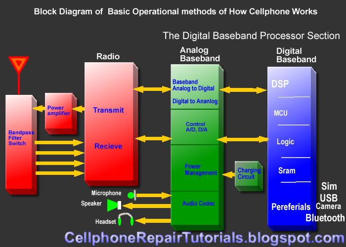
Cell-phone working principle
n this lesson we are going to take a brief familiarization of a typical block diagram of a cellphone.
Block Diagram can help us understand the flow of a certain part of a cellphone's circuit.
A Cell-phone handset is basically composed of two sections,
which is RF and Baseband Sections.
RF
RF refers to radio frequency, the mode of communication for wireless technologies of all kinds, including cordless phones, radar, ham radio, GPS, and radio and television broadcasts. RF technology is so much a part of our lives we scarcely notice it for its ubiquity. From baby monitors to cell phones, Bluetooth® to remote control toys, RF waves are all around us. RF waves are electromagnetic waves which propagate at the speed of light, or 186,000 miles per second (300,000 km/s). The frequencies of RF waves, however, are slower than those of visible light, making RF waves invisible to the human eye.
Baseband
In signal processing, baseband describes signals and systems whose range of frequencies is measured from zero to a maximum bandwidth or highest signal frequency. It is sometimes used as a noun for a band of frequencies starting at zero.
In telecommunications, it is the frequency range occupied by a message signal prior to modulation.
It can be considered as a synonym to low-pass.
Baseband is also sometimes used as a general term for part of the physical components of a wireless communications product. Typically, it includes the control circuitry (microprocessor), the power supply, and amplifiers.
A baseband processor is an IC that is mainly used in a mobile phone to process communication functions.
Basically Baseband also composed of to sections which is the Analog and Digital Processing Sections. So, we are going to separate each other for better and easier to understand.
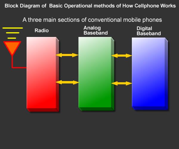
Cell-phone have three different sections which is the following.
I prepare this to be simple and easy instead of using or explaining it with deep technical terms .
In this manner, it is easy for us to understand the concepts and methods of how basically the cellphone works.
Cell-phone have three sections since baseband is differentiated by into two which is the Analog and Digital function while the RF section remains as a whole circuit section.. which is the following cosists.
1. Radio Frequency (RF Section)
2. The Analog Baseband Processor
3. And the Digital Baseband Processor.
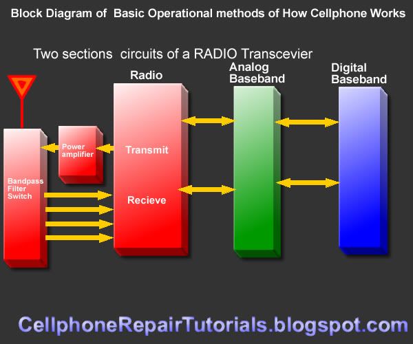
Radio Frequency Processing Section
The RF section is the part of the cell-phone circuit is also known as RF Transceiver.
It is the section that transmit and receive certain frequency to a network and synchronize to other phone.
The RF - A radio section is based on two main Circuits.
1 Transmitter
2 Reciever
A simple mobile phone uses these two circuits to correspond to an other mobile phone. A Transmitter is a circuit or device which is used to transmit radio signals in the air.and a reciever is simply like radios which are used to recieve transmissions(Radiation) which is spread in the air by any transmitter on a specific frequency.
The two way communication is made possible by setting two transmitters and two recievers sycronized in this form that a trasmitter in a cell phone is syncronised with the frequency of other cell phone's recieving frequency same like the transmitter of second cell phone is syncronised with the recieving frequency of first cell phone. So first cell phone transmits its radiation in the air while the other phone listens it and same process is present in the opposit side. so these hand held two cell phones correspond to one another.
the technology used in these days is a little bit different but it is based on the basic theory prescribed before. the today's technology will be discussed in later on.
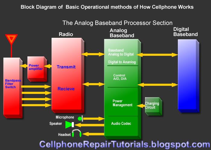
Analog Baseband Processor
A/D and D/A section
The analog baseband processing section is composed of different types of circuits.
This section converts and process the analog to digital (A/D) signals and digital to analog signals (D/A).
Control section
This is the section acts as the controller of the the input and output of any analog and digital signal.
Power Management
A power management section in mobile phones is designed to handle energy matters that is consumed in mobile phones. There are two main sub sections in a single power section.
• Power Distribution and switching section
• Charging Section
A power distribution section is designed to distribute desired Voltages and currenst to the other sections of a phone. this section takes power from a battery (which is figured commonly 3.6 Volts)and in some places it converts or step down to various volts like 2.8 V 1.8V 1.6V etc.while on other place it also
steps up the voltage like 4.8 V. this section is commonly designed around a power IC(and integrated circuit) which is used to distribute and regulate the voltage used in other components.
The Charging section is based on a charging IC which takes power from an external source and gives it to battery to make it again power up when it is exhausted. this section uses convertibly 6.4 V from an external battery charger and regulates it to 5.8V wile giving it to battery. The battery is made charged by this process and it is ready to use for the next session (a battery session is a time which is provided by the manufacturer of a cell phone for standby by condition of a mobile phone or talk condition.)
Audio Codecs Section
This section where analog and digital audio properties being process like the microphone, earpiece speaker headset and ring-tones and also the vibrator circuits.
Digital Baseband Processor
This is the part where All Application being process. Digital Baseband Processor section is used in mobile phones to handle data input and ouput signal like switching, driving applications commands and memory accessing and executing.
These are the parts and sections o a Digital Baseband Circuit were installed.
CPU
CPU( Centeral Processing Unit) The Central Processing Unit (CPU) is responsible for interpreting and executing most of the commands from the users interface. It is often called the "brains" of the microprocessor, central processor, "the brains of the computer"
Flash and Memory Storage Circuits
*RAM( Random Access Memory)
*ROM,Flash(Read Only Memory
Interfaces such as the following were also part on this section:
*Blutooth
*Wi-fi
*Camera
*Screen Display
*Keypads
*USB
*SIM-Card
Here a typical overview of a block diagram on latest mobile phone designs.
Various mobile phones have different concepts and design
on every aspects, but the methods and operational flow are all exactly
the same. It differs on how and what certain IC chips and parts they are
being used and installed to a certain mobile phone circuitry.
Block Diagram can help us understand the flow of a certain part of a cellphone's circuit.
A Cell-phone handset is basically composed of two sections,
which is RF and Baseband Sections.
RF
RF refers to radio frequency, the mode of communication for wireless technologies of all kinds, including cordless phones, radar, ham radio, GPS, and radio and television broadcasts. RF technology is so much a part of our lives we scarcely notice it for its ubiquity. From baby monitors to cell phones, Bluetooth® to remote control toys, RF waves are all around us. RF waves are electromagnetic waves which propagate at the speed of light, or 186,000 miles per second (300,000 km/s). The frequencies of RF waves, however, are slower than those of visible light, making RF waves invisible to the human eye.
Baseband
In signal processing, baseband describes signals and systems whose range of frequencies is measured from zero to a maximum bandwidth or highest signal frequency. It is sometimes used as a noun for a band of frequencies starting at zero.
In telecommunications, it is the frequency range occupied by a message signal prior to modulation.
It can be considered as a synonym to low-pass.
Baseband is also sometimes used as a general term for part of the physical components of a wireless communications product. Typically, it includes the control circuitry (microprocessor), the power supply, and amplifiers.
A baseband processor is an IC that is mainly used in a mobile phone to process communication functions.
Basically Baseband also composed of to sections which is the Analog and Digital Processing Sections. So, we are going to separate each other for better and easier to understand.
Cell-phone have three different sections which is the following.
I prepare this to be simple and easy instead of using or explaining it with deep technical terms .
In this manner, it is easy for us to understand the concepts and methods of how basically the cellphone works.
Cell-phone have three sections since baseband is differentiated by into two which is the Analog and Digital function while the RF section remains as a whole circuit section.. which is the following cosists.
1. Radio Frequency (RF Section)
2. The Analog Baseband Processor
3. And the Digital Baseband Processor.

Radio Frequency Processing Section
The RF section is the part of the cell-phone circuit is also known as RF Transceiver.
It is the section that transmit and receive certain frequency to a network and synchronize to other phone.
The RF - A radio section is based on two main Circuits.
1 Transmitter
2 Reciever
A simple mobile phone uses these two circuits to correspond to an other mobile phone. A Transmitter is a circuit or device which is used to transmit radio signals in the air.and a reciever is simply like radios which are used to recieve transmissions(Radiation) which is spread in the air by any transmitter on a specific frequency.
The two way communication is made possible by setting two transmitters and two recievers sycronized in this form that a trasmitter in a cell phone is syncronised with the frequency of other cell phone's recieving frequency same like the transmitter of second cell phone is syncronised with the recieving frequency of first cell phone. So first cell phone transmits its radiation in the air while the other phone listens it and same process is present in the opposit side. so these hand held two cell phones correspond to one another.
the technology used in these days is a little bit different but it is based on the basic theory prescribed before. the today's technology will be discussed in later on.

Analog Baseband Processor
A/D and D/A section
The analog baseband processing section is composed of different types of circuits.
This section converts and process the analog to digital (A/D) signals and digital to analog signals (D/A).
Control section
This is the section acts as the controller of the the input and output of any analog and digital signal.
Power Management
A power management section in mobile phones is designed to handle energy matters that is consumed in mobile phones. There are two main sub sections in a single power section.
• Power Distribution and switching section
• Charging Section
A power distribution section is designed to distribute desired Voltages and currenst to the other sections of a phone. this section takes power from a battery (which is figured commonly 3.6 Volts)and in some places it converts or step down to various volts like 2.8 V 1.8V 1.6V etc.while on other place it also
steps up the voltage like 4.8 V. this section is commonly designed around a power IC(and integrated circuit) which is used to distribute and regulate the voltage used in other components.
The Charging section is based on a charging IC which takes power from an external source and gives it to battery to make it again power up when it is exhausted. this section uses convertibly 6.4 V from an external battery charger and regulates it to 5.8V wile giving it to battery. The battery is made charged by this process and it is ready to use for the next session (a battery session is a time which is provided by the manufacturer of a cell phone for standby by condition of a mobile phone or talk condition.)
Audio Codecs Section
This section where analog and digital audio properties being process like the microphone, earpiece speaker headset and ring-tones and also the vibrator circuits.

Digital Baseband Processor
This is the part where All Application being process. Digital Baseband Processor section is used in mobile phones to handle data input and ouput signal like switching, driving applications commands and memory accessing and executing.
These are the parts and sections o a Digital Baseband Circuit were installed.
CPU
CPU( Centeral Processing Unit) The Central Processing Unit (CPU) is responsible for interpreting and executing most of the commands from the users interface. It is often called the "brains" of the microprocessor, central processor, "the brains of the computer"
Flash and Memory Storage Circuits
*RAM( Random Access Memory)
*ROM,Flash(Read Only Memory
Interfaces such as the following were also part on this section:
*Blutooth
*Wi-fi
*Camera
*Screen Display
*Keypads
*USB
*SIM-Card

Here a typical overview of a block diagram on latest mobile phone designs.
 |
Wideband – OFDM
Orthogonal frequency division
multiplexing (OFDM) is a multicarrier transmission technique that has
been successfully applied to wide variety of digital communication
applications. Although the concept of OFDM has been around for a long
time, it has been recently recognized as an excellent method for high
speed bi-directional wireless data communication. This technology is
used in broad cast systems such as Asymmetric Digital Subscriber Line
(ADSL), European Telecommunications standard Institute (ETSI), radio
(DAB: Digital Audio broadcasting) and TV (DVB: Digital Video
broadcastingTerrestrial) as well as being proposed for wireless LAN
standards.
OFDM efficiently squeezes multiple modulated carriers tightly
together reducing the required bandwidth but keeping the modulated
singles orthogonal so that they do not interface with each other. Any
digital modulation technique can be used on separate carriers. The
output of the modulated carriers is added together before transmission.
At the receiver, the modulated carriers are separated before
demodulation.W- OFDM will allow the deployment of 4 G wireless networks that enable phones to transmit data at rates of up to megabits per second.OFDM segment are according to frequency. It is a technique that divides the spectrum in to a number of equally spaced tones and carriers a portion of a users information on each tone. A tone can be thought of frequency. Each tone is orthogonal to the other. OFDM is also called multi tone modulation.
OFDM can be considered as a multiple access technique, because an individual tone or groups tones can be assigned to different users. Multiple users share a given bandwidth in this manner, yielding the system called OFDMA. Each user can be assigned a predetermined number of tones when they have information to send, or alternatively a user can be assigned a variable number of tones based on the information that they have to send.W-OFDM can overcome problems of high peak-to-average signal amplitude and fading due to multipath affects. W-OFDM enables the implementation of low power multipath RF networks that minimize interference with adjacent networks.
OFDM FOR MOBILE COMMUNICATION
OFDM represents a different system design approach it can be though of as combination of modulation and multiple across schemes that segment a communications channel in such a way that many users share it. Where as TDMA segments are according to time and CDMA segments are according to spreading codes ,OFDM segments are according to frequency. It is a technique that divides the spectrum into a number of equally spaced tones and carries a portion of a users information on each tone. A tone can be thought of a frequency, much in the same way that each key on a pain represents unique frequency. OFDM has a special property that each tone is orthogonal with each other. There will be frequency guard bands b/w frequencies so that they do not interfere with each other. OFDM allows the spectrum of each tone to overlap and because they are orthogonal they donot interfere with each other. This reduces the required spectrum.
OFDM is a modulation technique that enables user data to be modulated onto the tones. The information is a modulated into a tone by adjusting the tones phase amplitude or both. In the most basic form, a tone may be present or disabled to indicate a one or zero bit of information; however, either phase shift keying (PSK) or quadrate amplitude modulation (QAM) is typically employed. An OFDM system takes a data stream and splits it into N parallel data streams each at a rate 1/N of the original rate. Each stream then mapped to a tone at a unique freq and combined together using the inverse fast Fourier transform (IFFT) to yield the time-domain waveform to be transmitted.
For example, if a 100-tone system were used, a single data stream with a rate of 1 mega bit per second (Mpbs) would be converted into 100 streams of 10 kilobits per second (Kpbs). By creating parallel data streams, the bandwidth of modulation symbol is effectively decreased by a factor of 100. OFDM can also be considered a multiple access technique because an individual tone or groups of tone can be assigned to different users. Multiple users share a given band with in this manner, yielding the system called OFDMA. Each user can be assigned a predetermined number of tones when they have information to send, or alternatively, a user can be assigned a variable number of tones on the amount of information that they have to send.
OFDM can be combined with frequency hopping to create a spread spectrum system, realizing the benefits of frequency diversity and interference averaging property. In frequency hopping spread spectrum system, each users’ set of tones is changed after each time period. By switching frequencies after each symbol time, the losses due to frequency selective fading are minimized.OFDM therefore provides the best of the benefits of TDMA in that users are orthogonal to one another and CDMA-while avoiding the limitations of each including the need for TDMA frequency planning and multiple access interference in the case of CDMA.
Standard Definition Television
Television
systems that have a resolution that meets standards but not considered
high definition, this is what Standard-definition television or SDTV
refers to. This usually refers to digital television, especially while
broadcasting at the same (or similar) resolution as analog systems. In
ATSC, SDTV can be broadcast in 704 pixels × 480 lines with 16:9 aspect
ratio (40:33 rectangular pixel), 704 pixels × 480 lines with 4:3 aspect
ratio (10:11 rectangular pixel) or 640 pixels × 480 lines with 4:3 ratio
(and square pixels). The refresh rate can be 24, 30 or 60 pictures per
second. Digital SDTV in 4:3 aspect ratio has the same form as the
regular analogue TV (NTSC, PAL, PAL2, SECAM) excluding the ghosting,
snowy images and static noises but however with poor reception one may
encounter various other artifacts such as blockiness and stuttering.
Though ATSC and ISDB were originally developed for HDTV, they later
proved their ability to deliver multiple SD video and audio streams via
multiplexing, than to use the entire bit stream for one HD channel.
Eventually ATSC, ISDB along with ISDB were the standards used to
broadcast digital SDTV
Digital Audio Broadcasting
This Electronics Engineering Seminar Topic deals with the following:
Digital audio broadcasting, DAB, is the
most fundamental advancement in radio technology since that introduction
of FM stereo radio. It gives listeners interference — free reception of
CD quality sound, easy to use radios, and the potential for wider
listening choice through many additional stations and services.

DAB system is a rugged, high spectrum and power efficient sound and data broadcasting system. It uses advanced digital audio compression techniques (MPEG 1 Audio layer II and MPEG 2 Audio Layer II) to achieve a spectrum efficiency equivalent to or higher than that of conventional FM radio. The efficiency of use of spectrum is increased by a special feature called Single. Frequency Network (SFN). A broadcast network can be extended virtually without limit a operating all transmitters on the same radio frequency.
EVOLUTION OF DAB
- DAB has been under development since 1981 of the Institute Fur Rundfunktechnik (IRT) and since 1987 as part of a European Research Project (EUREKA-147).
- In 1987 the Eureka-147 consoritium was founded. It’s aim was to develop and define the digital broadcast system, which later became known as DAB.
- In 1988 the first equipment was assembled for mobile demonstration at the Geneva WARC conference.
- By 1990, a small number of test receivers was manufactured. They has a size of 120 dm3
- In 1992, the frequencies of the L and S — band were allocated to DAB on a world wide basis.
- From mid 1993 the third generation receivers, widely used for test purposes had a size of about 25 dm3, were developed.
- The fourth generation JESSI DAB based test receivers had a size of about 3 dm3.
1995 the first consumer — type DAB receivers, developed for use in pilot projects, were presented at the IFA in Berlin.
In short 1992 — 1995 — field trial period. 1996 — 1997 — introduction period 98 onwards — terrestrial services in full swingWearable Computers
Ever since the development of the ENIGMA (the first digital
computer), computers have inspired our imagination. In this period came
the World War II code breaking machine designed by Alan Turing, and Von
Neuman’s ENIAC which can be called dinosaurs compared to present day
PCs. In the earlier days, computers were so huge that it took an entire
building, or at least a floor to occupy one. Computers of that era were
very slow by today’s standards. In the non-ending struggle to increase
computing speed, it was found out that speed of electricity might become
a limiting factor in the speed of computation, and so it was a need to
lessen the distance that electricity had to travel in order to increase
the computing speed. This idea still holds true in modern computing.
By the 1970s, computers grew fast enough to process an average user’s applications. But, they continued to occupy considerable amount of space as they were made of solid blocks of iron. The input was done by means of punch cards, and later came the keyboard, which revolutionalized the market. In 1971 came the 4004, a computer that was finally small in size. The programmability of these systems were quite less. Still, computers had to be plugged directly in to AC outlets, and input and output done by punch cards. These computers were not built keeping users in mind. In fact, the user had to adjust himself with the computer.
This was the time when wearable computer (wearcomp) was born. In the 1970s, wearcomp challenged the other PCs with its capability to run on batteries. Wearcomps were a new vision of how computing should be done. Wearable computing showed that man and machine were no more separate concepts, but rather a symbiosis. The wearcomps could become a true extension of one’s mind and body.
In the beginning of 1980s, personal computing emerged. IBM’s PC and other cheaper clones spread world-wide like fire. Finally the idea of a small PC on your desktop that costed you quite less became a reality. In the late 1980s PC’s introduced the concept of WIMP (Windows, Icons, Mice & Pointers) to the world which revolutionalised the interface techniques. At the same time, wearables went through a transformation of their own. They were now eyeglass based, with external eyeglass mounts. Though they remained visible to all, wearcomps were developing principles of miniaturization, extension of man’s mind and body, secrecy and personal empowerment. Now, the only thing needed was an environment for them to flourish. People began to realize that wearcomps could be a powerful weapon in the hands of an individual against the machinery.
The 1990s witnessed the launch of laptops. The concept was a huge success as people could carry their PC wherever they go, and use them any time they need. A problem remained still. They still had to find a workspace to use their laptops since keyboards and mice (or touch-pads) remained.
During all these years of fast transformation, there remained visionaries who struggled to design computers that were extension of one’s personality, computers that would work with your body, computers that will be with you at all times, always at your disposal. In the last two decades, wearcomps grew smaller still. Now you have completely covert systems which would reside inside your average glasses.
One of the prevalent ideas in wearable computing is the concept of mediated reality. Mediated reality refers to encapsulation of the user’s senses by incorporating the computer with the user’s perceptive mechanisms, which are used to process the outside stimuli. For example, one can mediate their vision by applying a computer-controlled camera to enhance it. The primary activity of mediated reality is direct interaction with the computer, which means that computer is “in charge” of processing and presenting the reality to the user. A subset of mediated reality is augmented reality. It differs from the former because interaction with the computer is secondary. The computer must be able to operate in the background, providing enough resources to enhance but not replace the user’s primary experience of reality. Wearable computers have many applications centered around this concept of mediated / augmented reality as well as many other exciting applications centered around the idea of immediate access to information.
WIRELESS HD
WirelessHD
is an effort of the consortium led mainly by LG , Matsushita, NEC,
Samsung, SiBEAM, Sony and Toshiba to define a standard for the next
generation wireless digital network interface specification for wireless
high-definition signal transmission for consumer electronics products
and they intend to finalize on one standard by spring 2007. The
WirelessHD (WiHD) is designed and optimized for wireless display
connectivity thereby achieving high-speed rates from 2 Gbit/s to 5
Gbit/s for the CE, PC, and portable device segments in its first
generation implementation. This standard aids in uncompressed, digital
transmission of HD video and audio signals, making it like wireless
HDMI, in theory. data rates as high as 20 Gbit/s (compared to
10.2-Gbit/s for HDMI 1.3)are possible with its core technology,
permitting it to scale to higher resolutions, color depth, and range.
The signal will operate on the 60 GHz frequency band which currently requires line of sight between transmitter and receiver and apparently will sport the bandwidth required to support both current and future HD signals. This is far from the real aim of the WiHD, which would be maintain the elegance of the hang-on-the-wall plasmas and LCDs by tucking away the components and wires in a cabinet. The goal for the first line of products will be in-room, point-to-point , non line-of-sight (NLOS) at up to 10 meters. There much work to be done to improve interoperability among devices, and also to expand the capabilities of personal video players, PDAs, and other handheld devices.
The signal will operate on the 60 GHz frequency band which currently requires line of sight between transmitter and receiver and apparently will sport the bandwidth required to support both current and future HD signals. This is far from the real aim of the WiHD, which would be maintain the elegance of the hang-on-the-wall plasmas and LCDs by tucking away the components and wires in a cabinet. The goal for the first line of products will be in-room, point-to-point , non line-of-sight (NLOS) at up to 10 meters. There much work to be done to improve interoperability among devices, and also to expand the capabilities of personal video players, PDAs, and other handheld devices.
Subscribe to:
Posts (Atom)


